Recommended Casting Instructions
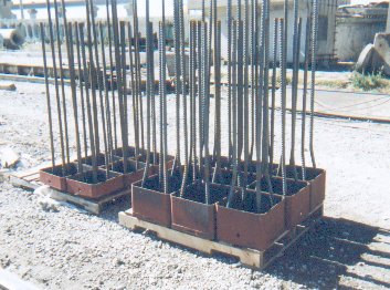
ASSEMBLY
- Male and Female splice plates are shipped palletized and are interchangeable. Threaded rebar anchors are shipped separately.
- Screw the bars into tapped holes in the back sides, making sure that the ends do not protrude through the plate face. The bent rebar is screwed into the Female splice half with the offset to the inside of the spiral per drawing.
- The outside of the Male plate and inside of the Female plate groove edges must be protected from concrete spills. Run duct tape around edges before placing in forms.
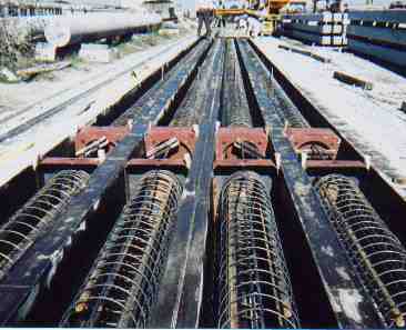
Installation
- The Female half goes on the top of the bottom segment; the Male on the bottom of the top segment. Place the halves 1-2 ft. apart in the forms with vent hole in the skirts facing up. If there is spiral to go inside Female rebar offset bends and over strands, place the turns inside first, pull strands, do initial tensioning, spread spiral (and/or stirrups). Support the splice rebar weight from kicking the splice faces back.
- Squaring:
a) With sufficient quantity, it may be more efficient to have jigs made.
b) Otherwise, spacers can be made, or use a framing square against the splice face and form sides. One man can check the square while another moves the rebar and ties it. Some precasters use strand clamps at the splice face without spacers.
AFTER CASTING
- Remove duct tape before burning strands off flush with splice plates so it doesn’t melt
- Grind plate surfaces flush so that no strand element protrudes, not even 1/32".
- Clean mating splice surfaces and grooves of all concrete before shipping.
It is important for successful splicing at the job site that the splice surfaces and
grooves are free from concrete and strand ends are flush -- inspect!
Recommended Driving Instructions
A note to estimators -- KIE-LOCK splices can be attached in 30 seconds; the relevant
time for splicing is dependant on how fast the top segment can be lofted into position
and placed to splice.

EQUIPMENT
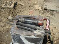
- Two rectangular locking bars with rounded noses are supplied for each splice for the circular key splices
- A drive plate is supplied for insertion in the female splice plate to provide a flat driving surface on the bottom pile segment. Normal hammer cushions are used.
- The locking bars are most effectively driven for large quantities of piles with an impact hammer, such as a Rivet Buster, with a "pin driver" or "ground rod driver" bit.
- For small quantities of splices or in close quarters, a 5 lb. sledge can be used without difficulty.
- No impact hammer is required for the LA DOTD and FDOT 24", 30” and 36" square splices.
DRIVING & SPLICING
- Check to make sure all splice mating surfaces are clean of concrete and strands are ground flush when piles are delivered.
- Insert drive plate into Female splice, loft, and drive bottom segment to waist height.
- Remove drive plate and clean surfaces of debris manually or with compressed air.
- After pick-up of top segment, clean off any dirt from Male splice surfaces and groove.
- Align pile segments axially, and fit the top pile (Male) into the Female recess of the bottom segment.
- . Make sure that splice faces to meet evenly and grooves match (look through side slots to check). Insert both locking bars in a clockwise direction. For 24", 30” & 36" sq. Splices: Insert four locking bars manually through the 4 entry holes on the sides and secure with the plugs that come in the splice. Disregard 7 & 8 below.
- Drive one locking bar about half way, then the other bar all the way, and come back and finish driving the first bar. The bars normally drive quickly and easily, but if high resistance is found at a certain point, the top pile segment needs to be realigned in the direction of locking bar tip location
- If using an impact hammer with recessed bit, the locking bars will still protrude a little after hammering – finish driving with a sledge. The locking bar length is calculated to have some protrusion when fully driven – the inside corner of the end of the bar should end up close to the outside edge of the splice plate.
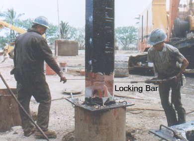
It is important to have splice surfaces that are clean and flush, and that the top pile segment is aligned properly.
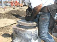
Removing the Drive Plate
Lock Bars and Air Hammer
SPLICING TIMELINE
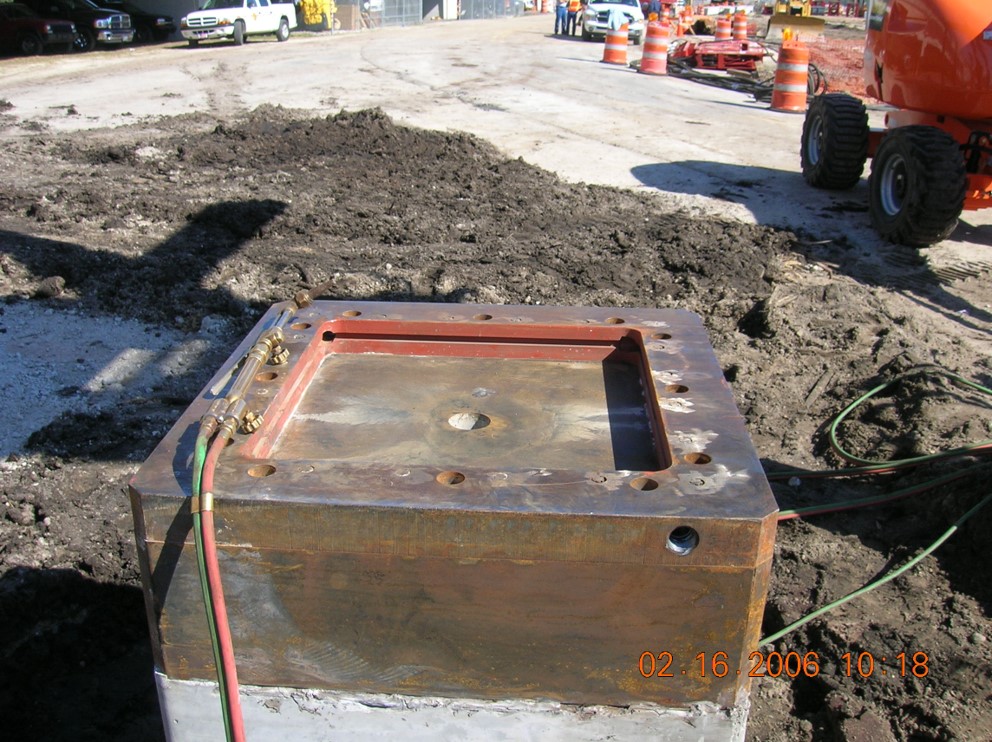
Female portion on lower driven section.
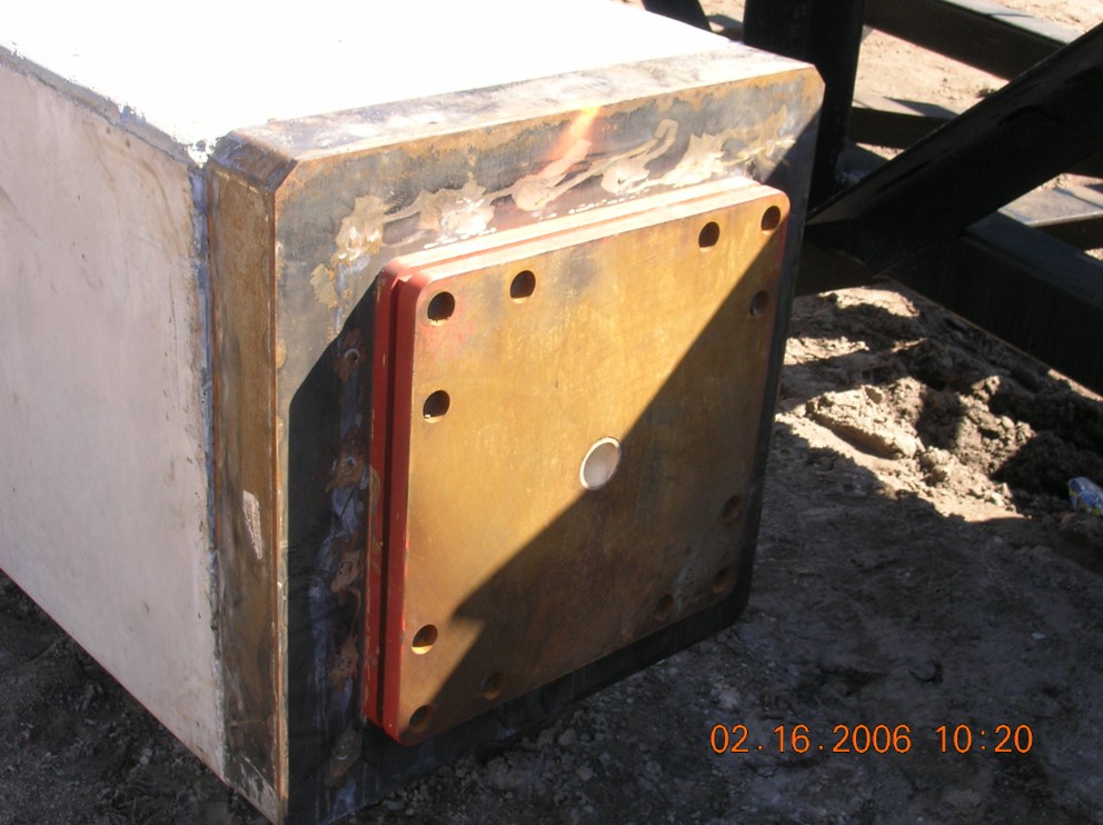
Male portion on upper pile section.
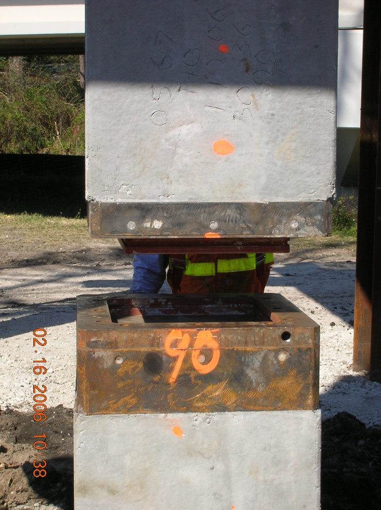
Lower upper pile section onto already driven lower section.
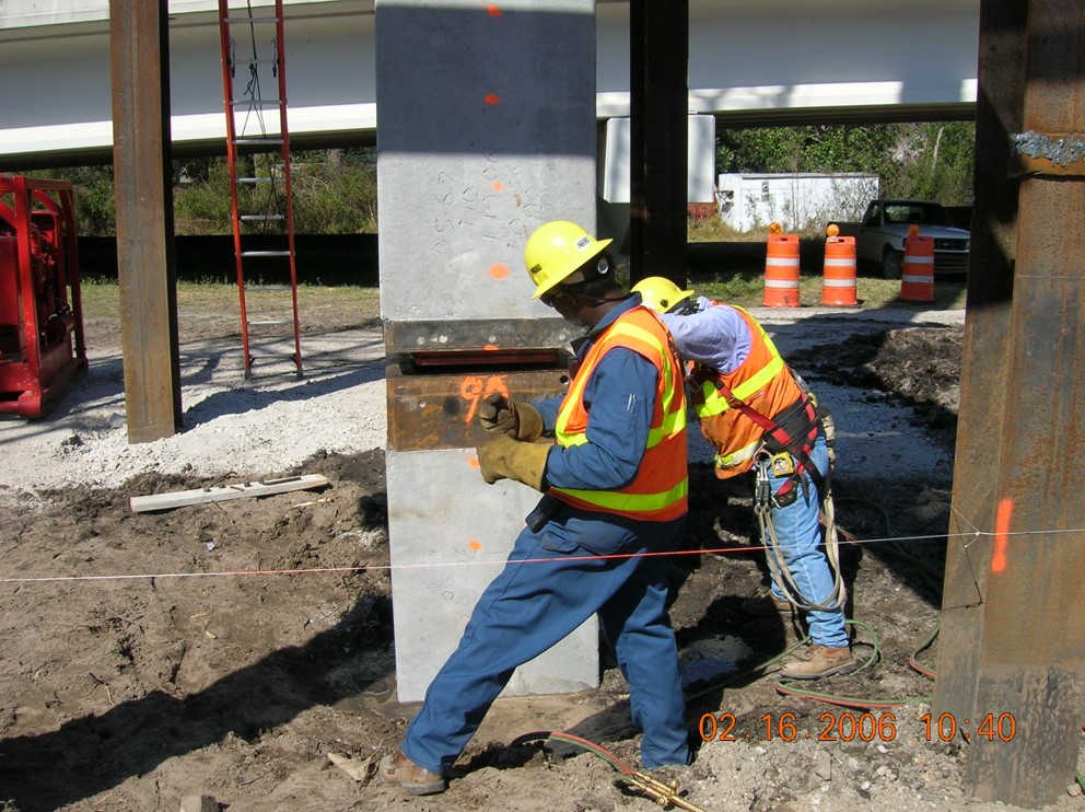
Align pile, the 3 formed faces line up and finished faces match.
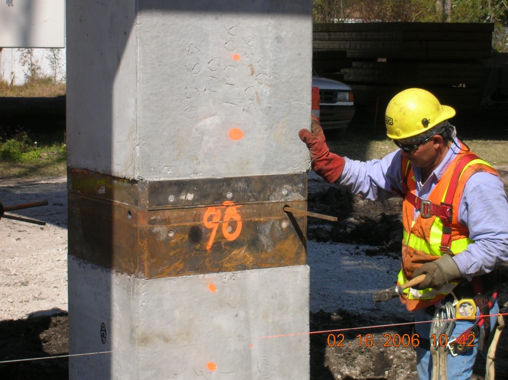
Drive square pins and all four corners with a 5lb sledge hammer.
Download PDF Instructions
