
D-01
Pile Configuration
Pile dimensions, strand quantity and location, reinforcement, and concrete strength are considered when determining the appropriate splice configuration.
KIE-LOCK pile splices are engineered around the structural requirements of each pile system. Pile size, reinforcement, loading, concrete strength, and project requirements are considered to deliver a connection designed for reliable performance.
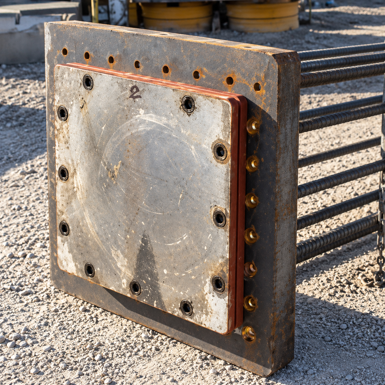
Pile designs vary by project, region, application, and structural requirements. KIE-LOCK configurations can be adapted around the requirements of the pile system.
Pile dimensions, strand quantity and location, reinforcement, and concrete strength are considered when determining the appropriate splice configuration.
Main plate thickness, locking bar size, reinforcement, and connection geometry can be configured to meet the requirements of the application.
Load-bearing components are evaluated for the required pile capacities, including tension, compression, and bending.
Rebar anchorage and pile-end reinforcement are engineered to integrate the splice with the surrounding pile structure.
Engineering can address applicable ACI, AASHTO, DOT, building-code, and project-specific requirements.
Review pile dimensions, reinforcement, capacity, application, and project requirements.
Determine the appropriate plate, locking-bar, reinforcement, and anchorage configuration.
Evaluate the connection against the required tension, compression, and bending capacities.
Produce the required splice configuration along with applicable drawings and engineering documentation.
KIE-LOCK load-bearing components are designed and evaluated around the structural demands of the pile system.
Corrosion performance depends on the environment and installation conditions. Research and field evidence provide important insight into the long-term performance of steel piling components in appropriate underground conditions.
CalTrans reported no significant corrosion in steel pipe piles extracted from the Cypress Viaduct in Oakland after more than 35 years, despite high chloride and sulfate levels and low soil resistivity.
National Bureau of Standards studies concluded that steel pilings are not significantly affected by corrosion in undisturbed anaerobic soils, regardless of soil type and properties.
Steel splices can be located within the concrete pile zone in previously undisturbed soil and below ocean and river scour lines.
Supporting National Bureau of Standards and CalTrans reports are available for engineering review.
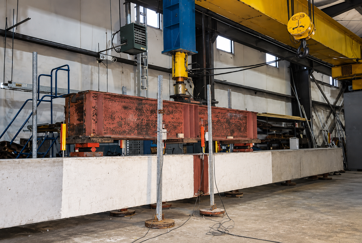
KIE-LOCK design methodology has been supported by structural testing across multiple pile sizes, configurations, and applications. These tests help validate the engineering approach used in KIE-LOCK splice designs.
Detailed test reports, calculations, and supporting engineering information are available for project review.
Tell us your pile size, quantity and timeline. Our team will get back to you on pricing and availability.